Encoder Circuit
Using the given (infrared) encoders is not too hard with a little extra circuitry.
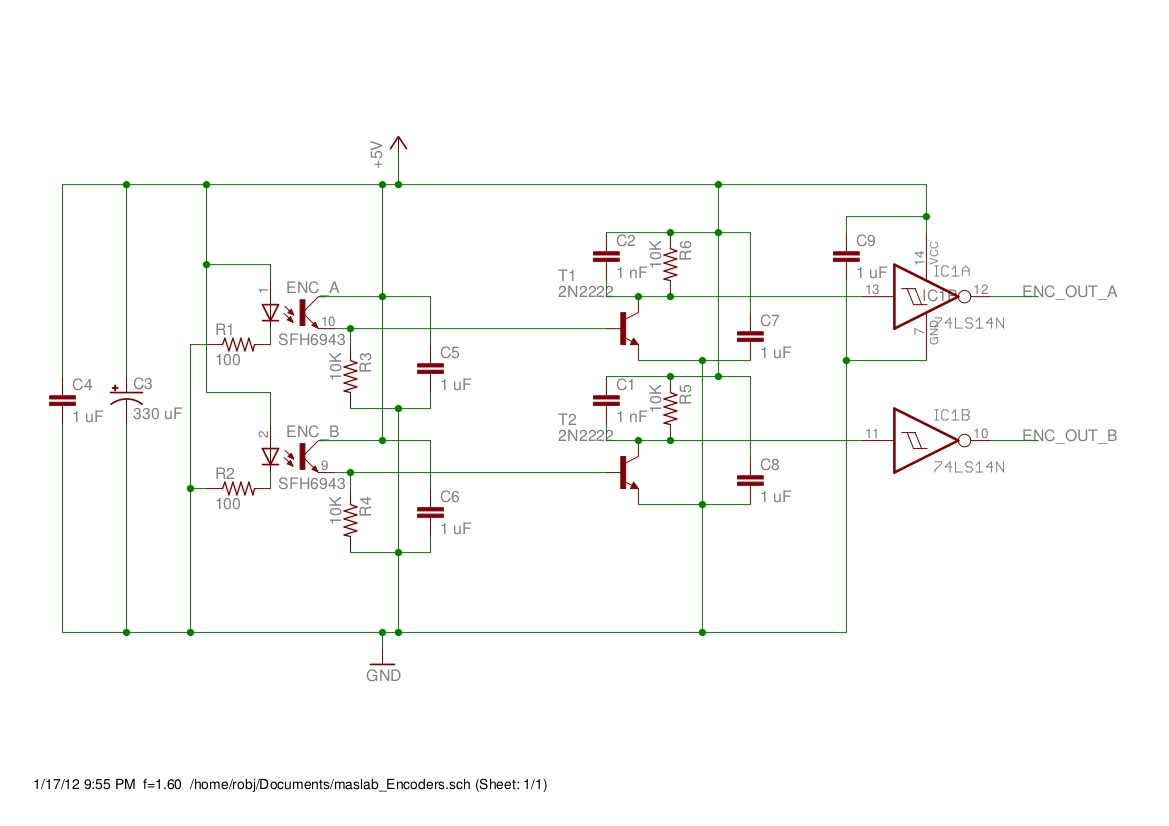
Schematic: Eagle
The LEDs are pretty straightforward (green and orange wires): I run the LEDs with 100 ohm resistors off the 5v rails.
The photoTransistors are a little more complicated. The datasheet says they shouldn't get a pull down resistor smaller than 10k so that's what we use. This response is not great, so I put this into the base of another NPN (2n2222). I pull up the 2n2222 (no real reason, I wanted to switch things up a little) not with just a resistor but with a RC pair. This made the output a little less 'jumpy' because the cap needed time to charge before the transistor could pull its output down. I then put this output into a Schmitt trigger (a 7414 works).
This produces something that works IF you use lots of bypass caps. I have tried fewer bypass caps than this and it does not work (the channels interfere). If you hook both up and get garbage values you need more bypassing. C3-C9 are all bypass caps so their values are approximate. C4-C9 are metal film caps and cannot be replaced with electrolytics. The bypass caps near the transistors need to be as close as possible to their respective transistors or you will get interference.
If you make one of these and have trouble, or make a few modifications feel free to shoot me an email. (robj)
