Team Two/Final Paper
February 3rd, 2012
== Final Paper ==
Rufus McNasty III, a champion amount his family and hometown friends, was named for his late father. Once his mother-bot saw the fire in his web cam, she knew he would be worthy to carry on the McNasty family name his father so proudly toted. Throughout his life he sought to prove himself amount the ranks of the greatest bots to ever run Python and to bring everlasting glory to his family line. All of his lifetime accomplishments culminate today in his final test. Now, as he looks forward and sees his robo-competitors, he feels no fear, as he is mostly just acrylic and metal, but he stands tall and ready to take on the world.
This is the story of how Rufus McNasty III came to be...
Overall strategy
Our overall strategy was to a) implement a robust mechanical design that would give the software some tolerances, b) design software that was complex enough to efficiently find and differentiate walls and balls, but simple enough so that the robot didn’t have to map the field or locate a ball with high accuracy, c) move along a wall if a ball is not in sight, or drive towards a ball if it detects one, d) after a certain period of time, launch all collected balls across the yellow wall, and e) deactivate the robot at the end of three minutes.
Mechanical Design and Sensors
From the beginning, we knew we wanted a robust robot design, none of that hodge podge sheet metal and pop rivets. We wanted the design to also give some slack to the programmers. We figured that the software team (not that they couldn’t) would not have time to perfect the vision code, making it near impossible to find a ball and drive directly towards it. We also wanted to make launching a ball as simple as sending a command to a servo.
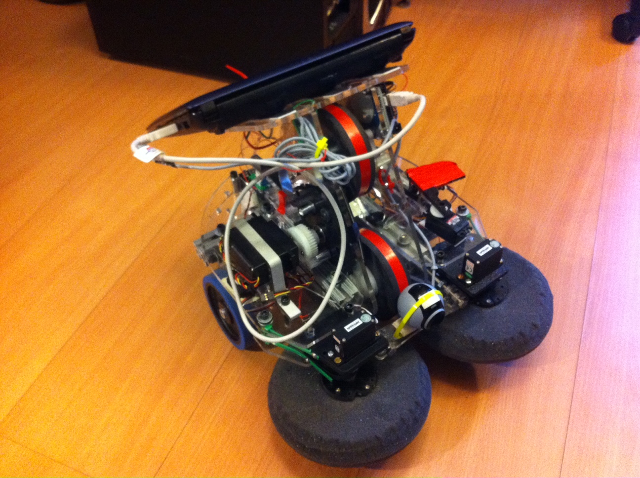
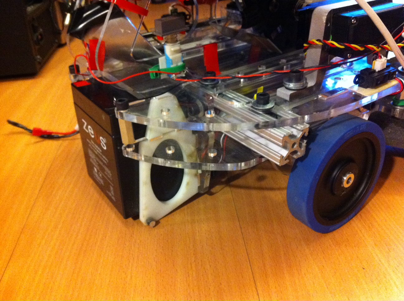
The base of our robot is made of two sheets of laser cut acrylic with 80-20 spacers in between to secure and support the weight of the robot. Attached to the base are the wheel motors and wheels. They were positioned in the center sides of the robot to allow us to turn in place. The third point of contact that the robot has to support itself is in the rear where the battery is stored. The battery box, which is made from two laser cut Delrin pieces, acts as a slider on the ground. There is only one point of contact and because the Delrin has a low coefficient of friction, it slider very freely. Because of the weight of the battery and the positioning of the laptop, which we discuss later, the center of mass is always behind the axis of the wheels (even when accelerating from moving forward to backwards) keeping the robot stable.
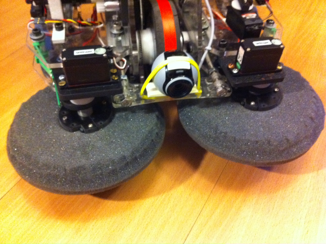
To give our programmers the tolerances that we talked about before, we decided to go with a street sweeper design. The design consisted of two rotating foam disks that are suspended above the ground such that a ball, when placed under, would be “grabbed” by the foam and forced to move in the direction of the spin. The disks spun in opposite directions and forced the balls to move towards the center of the robot. They were actuated via two servos directly connected to the foam disks with no gear reductions. We didn’t need the disks to spin fast. Each servo/disks assembly was mounted on the base through two pieces of abs plastic that were hinged. On the other side of the hinge was a bumper switch. This way when the spinning foam disks bumped into a wall, the abs would rotate back a bit and bump the switch. This signal was then used by the programmers to detect when the robot was against a wall.
To pick up the balls and get them into our robot as well as launch the balls, we opted for a sort of baseball pitching machine design. Two four inch wheels rotate opposite each other and are oriented such that there isn’t enough space between the wheels to allow for a ball to fit. The result is when they are spin at top speed, a ball is accelerated from the friction produced by the wheels. The wheels themselves are made from solid 1 inch thick PVC (that we water jetted) and wrapped in a denser foam that the sweeper disks (also water jetted). The final layer are a few rubber bands to add more friction. The lower wheel is also spaced above the ground so that when a ball is pushed under from the sweeper disks, it is accelerated up a ramp into the queue of the robot.
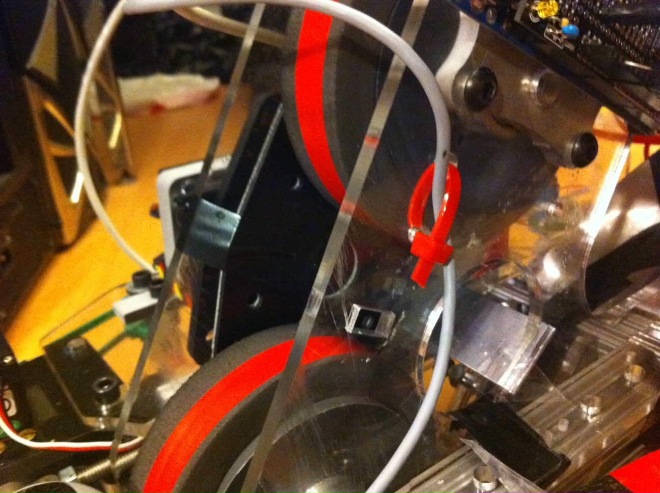
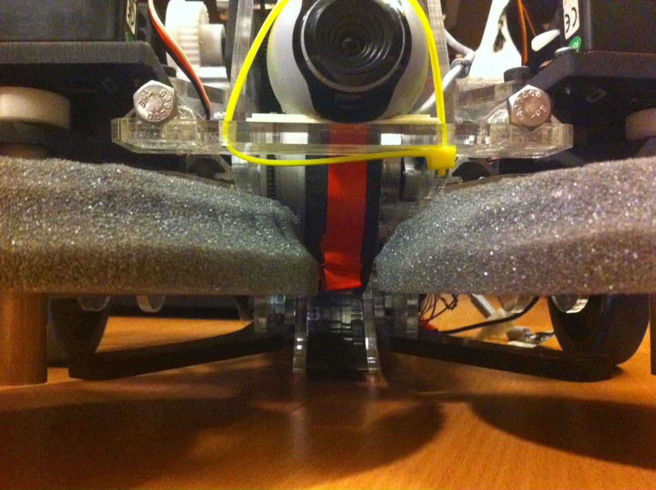
The launcher assembly is held together by two vertical acrylic sheets which also support the arduino (attached to the side) and the laptop which sits on Velcro atop another acrylic plate straddling the two vertical sheets. The launcher is actuated by a large server with high torque that is geared up to produce higher rotational velocity in the launcher wheels.
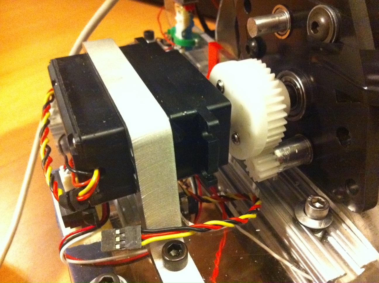
Finally, the balls that were waited in the queue were forced into the launcher by a servo with a simple arm attached. It simply forced the balls over a small lip that prevented them from rolling in. The only sensors we used were the two bump sensors, two IR sensors located on each side facing out and the web cam which was located in the front.
Software Design
As stated previously, we came into MasLab with little robot programming experience. In fact, none of the coders had any experience programming robots outside of 6.01. This led to a mentality of keeping our code as simple as possible throughout the process. The code was split up into two pieces: vision and behavior.
The vision was built to be simple and fast. Utilizing the python wrapper for the opencv library, the vision processing consisted of three methods each with similar components. First, taking the input image, this is re-sized to be 120 by 160 pixels. While making the robot near sighted, this allowed the algorithm to run much faster. Next the image was converted from RGB to HSV and then split into it’s separate bands. Then we applied thresholds to the bands to filter out the hue we were looking for as well as the saturation levels of our target. Next the algorithm scanned for high concentrations of color and saturation with large levels of contours. These “target regions” were then given numeric values for their distance from the center-line of the camera and then either processed as a yellow wall, blue wall or red ball.
In the case of the yellow wall and red balls, the algorithm took the highest concentrations and returned their value as the distance away from the center. This meant if the robot had a cluster of balls on one side of the center-line, it would travel towards them instead of towards an individual ball. With the yellow wall, the center of the wall was returned to allow the robot to aim it’s self towards the wall. Lastly the blue wall data was taken to draw a rectangle over the area above and including the blue wall which would not be processed in future runs of the image.
The most difficult part of our vision code was the process of calibrating the sensor to allow for accurate detection and elimination of false positives. Lighting and angle changes often threw off our thresholds and hurt our robot’s vision. We tried to maintain large bands of acceptance, but this often resulted in misinformation. The most difficult portion of the code was determining if there was no wall or ball present.
The behavior was constructed as a simple state machine with four separate states: “Collect Balls”, “Find Yellow”, “Launch Balls” and “End Game”. The four states were determined to be the simplest way to have the robot perform the desired functions. As soon as the robot initialized it began to look for red balls and collected them. When no red balls were in sight, he would then follow walls until more red balls came into sight. The state would run until either the queue was full (which was about 4-6 balls) or a certain amount of time, which we later deemed to be about 45 seconds, expired. At this point, the robot moved into the next state, which was “Find Yellow”.
In the “Find Yellow” state, the robot moved towards a yellow wall if it was in sight or followed walls until a yellow wall was seen. A time out was implemented in this state if the yellow wall was not found after a while where the robot would move randomly about for about ten to fifteen seconds before looking for the yellow wall again. Once the yellow wall was found, Rufus uses both bump sensors to line up perfectly with the wall. At this point he was switches into the “Launch Balls” state, where he fires one ball a second for seven seconds, account for any balls that may have been collected not seen by the camera. This would come from the fact that the width of collecting balls was actually greater than the width of the camera’s vision. After launching the balls, the robot would switch back into the “Collect Balls” state.
Rufus’ final state was an “End Game” state. This state is activated after a certain amount of overall time has passed. For the competition we decided to initiate this state at the two minute mark. In this state, Rufus stops whatever he’s doing and begins to look for the yellow wall. After finding it, he launches any balls he may have in his queue and then move towards trying to collect balls that may still be on our side until time runs out. Overall, the development and construction of the code was done keeping simplicity in mind taking advantage of the mechanical advantages Rufus was provided with.
Overall Performance
After a last week rush and a final all-nighter, all the code was written and all the parts machined, Rufus was born as his creators somewhat imagined. In terms of mechanical design, most of the implemented parts worked as envisioned. The foam spinners on the front of the robot successfully collected balls at a relatively wide range (a range that was in fact wider than the field of vision). The launcher worked as expected as well, with the bottom wheel successfully kicking up balls back into the queue and the overall launcher launching balls over walls.The only physical part of the robot that didn’t quite work as anticipated was the front bump sensors that were supposed to engage whenever the foam spinners ran up against a wall. The idea was that the bump sensors could go off at any angle, but in practice in turned out that they could be activated by any angle except for when a wall was immediately in front of Rufus. While this angle didn’t come up too often, it certainly was a major physical malfunction. Other than that, the robot’s physical performance pretty much went as planned.
Unlike the physical parts however, the software never really worked as originally planned. On top of our inexperience, there were other factors that contributed to Rufus not behaving exactly as anticipated. For one, Rufus was not completely machined until the day of impoundment. This resulted in our coders only having a few hours with the finalized robot to test the final code. Unfortunately, there was not enough time to debug all of the code and this clearly showed in the early rounds of the competition. The biggest example of this occurred in our very first match when our robot ran well over 3 minutes and would not stop. Fortunately we were able to find where this problem right after the match and fixed this for the quarter- and semi-final rounds. Finally, the ultimate problem that prevented Rufus from behaving as we wanted him to was that we were never able to get his vision working as well as we wanted. By the final competition, Rufus could somewhat reliably detect red balls about 70% of the time. His ultimate downfall however came from the fact that we could not reliably detect yellow. This resulted in Rufus ultimately staying in the “Find Yellow” state throughout the competition if he ever did manage to collect enough balls to fill up the queue. Overall, Rufus’ behavior was about 70% as complete as we were hoping for by the time the competition began. If given an extra week to play and debug the code, we really believe Rufus could have legitimately competed for the MasLab crown.
Suggestions for future teams
If we were to give future MasLab teams any advice on their robots, the main thing we would stress would be to finish machining the robot with at least a week to spare in order to have time to debug any problems with preliminary code as well as coming up with code that they may not have foreseen as necessary when originally coming up with the code.
