Team Fourteen/Journal
Contents |
Day 1
Productive things: shop training completed. Not so productive things: trying to get maple to work
Day 2
Got maple to run a program. *round of high fives* The problem was that we couldn't change the serial port, because maple was not being recognized by the tablet. Useful link here if you're having trouble: http://forums.leaflabs.com/topic.php?id=73#post-788. Completed most of the wiring for the kitbot. Later in the evening the whole team attended the solidworks workshop.
Day 3
Completed wiring for kitbot and got started on some solidworks sketches. Sent in models for motor hub and some sensor. However, later in the day maple stopped responding to the tablet. Ubuntu was installed. Still no response. Nchinda stayed up very late.
We can 3d print stuff accurately, Yay. Ask if you need help.
Day 4
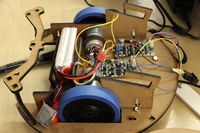
Started using assembly to put together kitbot on solidworks. Then a tentative robot base was created out of MDF using the laser cutter.
Huzzah maple is fixed, and we were able to make the motors move. Bad wiring was part of the problem. We can communicate using eclipse/java code but we can't download code using maple ide on any OS (Win, Ubu, Mac). John (supervisor guy) can though which is strange as heck.
Beginning to use MaslabGL for image processing.
Day 5
Supports for the top part of robot were laser-cut, but not put together since we were waiting on brackets.
Day 5.5 (Sunday 1/12)
Brackets have arrived! So the robot was put together. However, a noticeable amount of play means we will need to epoxy the hell out of this bad boy.
A decision was made to go for an archimedes screw instead of a a pulley. Apparently there will only be one ball size in use too, that makes this easier.
Day 6
A solidworks model of the archimedes screw was attempted, but not finished since all team members are inexperienced with the program. Ideas for the screw's construction included pvc or wood for the pole, then welding wire or pipe strapping for the spiral region.
Day 7
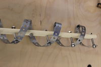
The archimedes screw was built out of thin pvc pipe (found in a closet in MacGregor), and pipe strapping bought at Home Depot in the afternoon. Surprisingly, Home Depot did not have size 4-32" lock nuts, and 6-32" was the smallest size they had. M6 x 60 Hexagon Head set screws and M6 Hexagon full nuts were used to secure the strapping to the pole. The next step is cutting out wooden "walls" for the screw and attaching a motor.
Day 8
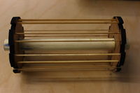
The top ball dispenser was constructed, it looks like a wheel with cutouts at the edge, to which rubber bands will be attached. We plan to position it 3/4 of the height of the ball above the top base. The rubber bands will provide enought traction to move the balls onto a small aluminum ramp and into the reactor. The dispenser is constructed out of MDF, with a PVC middle pole. Since the number of motors and sensors we are using is increasing, it would be better to have a base and sub-base. The sub-base will host the wheel motors and the ramp, and the base will host the ball-catcher motor. The two bases will be attached by five wooden stilts, of length 4". The solidworks models of these parts was completed later in the day.
Day 9
We decided to make the top and bottom dispensers the same size, since there doesn't seem to be any need to make the bottom one bigger. Also writing code for color recognition.
Day 10
Nchinda was so hot that the wire burned when he touched it. He was so hot that the wire got turned on by him. Nchinda was so hot that the wire melted.
Day 11
The solidworks model of the entire robot was finished, with the exception of the placement of the top and bottom ball-catchers. We now plan on using pipe strapping instead of a wooden motor mount to position the bottom motor, and a wooden block + motor mount for the top, which I don't think merits to be shown in the CAD. The sub-base, base, top base, and their supports were laser-cut.
Day 12
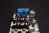
We machined a rod to attach the motor to the archimedes screw pvc pipe, and we expect to get it moving by the end of the day. The kitbot now uses the camera to identify edges, and by the end of the day should follow the wall. Hopefully, after this is done, we will transfer the motor controllers and wiring to the robot base and sub-base.
Day 13
Two more rods were machined to be attached to the ball cacher and dispenser. A ramp was guillotined of aluminum sheeting downstairs at the Edgerton center. The sides are turned up by 1" to prevent the ball from straying.
Day 14
Today we plan to finish transfering the wheel motors/wiring to the base of our real robot. Once this is done then it will be easier to figure out where to attach the ball catcher's motor.
Day 15
The various bases were put together and gorilla glue from Hex ToolCom was used to make sure several pieces didn't fly off when we carried Brobot (???someone confirm this name???) to the sponsor dinner. The day was spent cutting out the top ramp, wiring the controllers, and creating a "fence" for the balls on the top base.
Day 16
A final design for the ball sorter on the top of the robot was decided upon. CADing commenced and was completed. A combination of aluminum and MDF will be used in conjunction with a servo to create two separate paths for the balls to fall down when they are brought to the top. Green balls are stored on left, and reds on the right.


