Team One/Final Paper
Contents |
Overall Strategy
Our team’s goal throughout was to be capable of executing every task in the competition. This caused a very long and arduous process for the mechanical designers. Therefore, independent electronics and hardware tests were done on the kitbot as the final design date was uncertain. Further, the software team set up modular programs to be ready to run and test as each level of the robot became available. In order to allow for ambitious goals, mechanical design was also broken up modularly. Our robot had three levels, each with some independent functions along with integrated functions when balls had to pass between two levels. Each level was placed at the height required for it’s respective task. The camera would be placed on the front of the robot above the collection mechanism, facing forward angled at the ground and combined with sonars would provide the robot with the ability to sense its environment and ball locations. An roller mechanism with teeth connected by stretch rubber bands would pull in balls in the robots path towards an archimedes screw which would lift the balls up to the top level. There they would be sorted based on color and put in their respective compartments. The red compartment would be elevated enough to drop red balls over the opponents walls while the green compartment was elevated so that it could deposit balls in both levels of the reactor. The main compartment would directly align with the top of the reactor, but a trap door would be placed in the floor of the compartment so that we had the option to drop individual balls down and direct them to the bottom of the reactor. We also intended to have mechanism on the second level for silo collection and deposit of collected balls, allowing for integration of balls collected from the silo with the flow path of the rest of the balls. All 2d parts would be made with the laser cutter and the rest would be machined in a combination of the IDC machine shop, David’s UROP lab, as well as Evan’s.
Software
Mechanical
Level 1: Chassis and collection
The base level of the robot was designed to be able to house a drive-train, some electronics and the collection mechanism. Two diametrically opposed cut-outs allowed for the wheels to be placed along the robot’s centerline, thus allowing for rotation on center making it easier to navigate spaces of limited size. Originally this decreased our region of stability for the robot as it would leave a small triangle, made by our three points of contact, in which the robot’s center of gravity would have to remain. However, three well placed casters around the base of the robot solved this problem and did not cause any suspension issues. We ultimately decided that our motors were powerful enough to do direct drive and also placed our electronics on the second level where space would be more abundant and offer more access for wiring. On the front of the chassis, a cut out was made out of which a small ramp extended. The roller mechanism, attached to columns fixed to the chassis, would pull balls in, force them over the ramp, down another ramp so that they would fall into the entrance of our Archimedes screw. Every layer had a center cut-out to allow for the Archimedes screw to draw balls up the full height of the robot.
Level 2: Silo collection, electronics, and lower reactor deposit
With a center cut-out for the screw, level two’s perimeter was full of electronics and assorted mechanism’s to aid collection and deposit. Right above the roller sat a servo driven arm with an adhesive attached to its paddle. This would be used to pick up balls from the silo. The robot would position itself. The arm, appropriately elevated to collect from the silo would rotate out hopefully adhering to the ball. A second servo driven arm was placed perpendicularly to the collecting arm so that it could rotate very slightly above the top face of the collecting paddle and scrape the ball off of the adhesive and directly into a hole in level 2, placed right next to the collecting arm. The hole was also placed so that the ball would fall on the ramp behind the roller, allowing the ball to join the path of other collected balls, rolling towards the Archimedes screw. Deposit into the base of the reactor would also happen at level two. A trap-door in the level three would lead balls down a vacuum hose guided toward level two and off of the robot toward the floor. All wiring and most electronics placement was done on level two, including motor controller whose wires extended through holes in the floor to the drive wheels on level one, and the maple.
Level 3: Sorting and ball deposit
Upon exiting the Archimedes screw, balls would be directed upon an inclined plate towards a rotating jaw. Using a color sensor, the jaw would rotate to the side of the ball’s respective color. The ball would roll out of the jaw, onto a ramp, fall off of the ramp onto its colors compartment on level three which was also inclined. This incline would direct ball’s in the direction along which they would be deposited. The red balls would be deposited from the back as dropping them over the opponents wall required less precision and so the camera was less necessary. The red ball compartment had an extended base so when the robot was at the walls, falling red balls would be guaranteed to fall over the wall on not on our side. A servo driven gate would open up when the balls were ready to be dropped. On the other side, green balls fell onto an oppositely inclined compartment. This choice of direction was motivated by our need to align with the reactor and this required the camera. Unlike the red balls, the flow of green balls was to be controlled so that individual balls were sent out one at a time. The compartment incline directed balls to two upward facing roller mechanism offset from one another at a little under the balls diameter similar to the mechanism seen in batting cages. As balls hit the frictional and compliant surfaces of the rollers, they would be forced through the rollers one by one. A trap door was placed in front of these rollers. When open, green balls could fall through to the base of the reactor. When closed they would roll directly into the top level of the reactor.
Added Layers and structures
Right above the Archimedes screw, a small fourth level was added. This level housed the motor that drove the Archimedes screw, as well as the servo that drove the sorting jaw. It also had a mount for the tablet. This entire level was mounted on stilts attached to level 3.
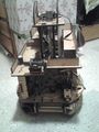
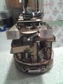
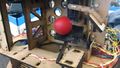
Photos
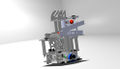
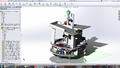
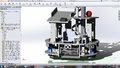
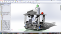
CAD Model
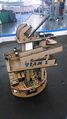
Front View
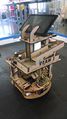
Back View
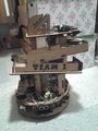
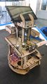
Side View
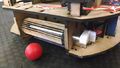
Roller
Sticky paddle


Advice for Next Year
- Get mechanical part done 1-2 weeks before the final competition, or at least finalize vital parts (i.e. the camera and wheelbase) so the code can be tested ASAP.