Quadphase encoders
From Maslab 2011
(Created page with "== Encoder kit contents == * 2 encoder boards * 2 1uF capacitors (surface mount, smaller brown one, white strip). Solder these in C1 on each board. * 2 10uF capacitors (surface ...") |
|||
| Line 30: | Line 30: | ||
'''Be sure to test your encoders to make sure they not only work, but are reliable. Try counting revolutions in both directions and at different speeds.''' | '''Be sure to test your encoders to make sure they not only work, but are reliable. Try counting revolutions in both directions and at different speeds.''' | ||
| + | |||
| + | [[image:Encoderfront.jpg]] [[image:Encoderback.jpg]] | ||
Latest revision as of 21:57, 24 December 2010
Encoder kit contents
- 2 encoder boards
- 2 1uF capacitors (surface mount, smaller brown one, white strip). Solder these in C1 on each board.
- 2 10uF capacitors (surface mount, larger brown one, clear strip) in C2.
- 4 220ohm resistors (surface mount, labeled 2200) in R1 and R2.
- 12 10K resistors (small surface mount components in a strip, labeled 1002) in R3-R8.
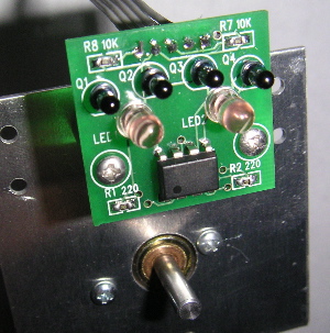
- 2 TLC352 comparators (8-pin chip) in U1. Make sure that pin 1 (nearest the dot) is in the square hole on the board, nearest the printed notch.
- 8 QSC114 phototransistors (smaller, black lens) in Q1-Q4. Make sure that the flat side matches the drawing on the board, and that the shorter lead is in the square hole. These should be put in as far in as they go, and as straight as possible.
- 4 IR LEDs (larger, clear lens) in LED1 and LED2. Again, check the flat side and the lead length for orientation. These must also be flush against the board and as straight as possible.
- 4 spacers. Find screws and screw the encoder to the motor mount with the spacers.
Assembly
- Solder the components to the boards as indicated above. Plastic guides are available to help align the phototransistors and LEDs; ask the staff to borrow one. First insert the components in the board, paying attention to orientation. Then, slide the plastic guide over them. Try both sides; one is easier to insert and remove. Solder the components, and remove the guide. Remember to return it to one of the staff.
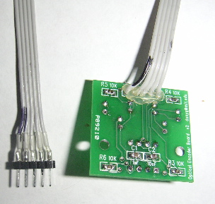
- Solder a 5-wide ribbon cable into the connector on the back of each board, and assemble the connector on the other end with male header. Pay attention to the ground wire (the square hole, labeled GND, backwards by mistake) for orientation when plugging it in, and mark the wire near the connector if necessary. Put hot glue around the joint of the cable and board- without this, it may break after flexing a few times.
- Punch two holes in each motor mount for the encoders, if needed. The holes should be 0.74" above the center of the motor shaft, and 0.9" apart.
- Put tape on the back of the encoder or the motor mount to make sure that nothing is shorted. Add washers if necessary to keep the encoder from touching the motor mount.
- Print and mount the encoder pattern (encoder.ps) to the wheel. You can mount it first to a circular disk cut out of cardboard, then glue that to the wheel.
- Screw the wheels on so that they are as close as possible to the encoders, while not scraping against them. You may even need to press your wheel hubs in further, but make sure the set screw is still accessible. Finally, when connecting the encoders, make sure that the ground wires are going to the "-" pins on the orcboard.
You can print the pattern on athena with "lpr -Pee08 encoder.ps". That encoder pattern provides 12 ticks per revolution. If you need higher resolution, you may experiment with the triple-res version (encoderhighres.ps). However, be warned that your component alignment must be extremely accurate for this to work reliably.
To emphasize, the most important factor is the alignment of the LEDs and phototransistors. Positioning also matters; the hole measurements above are calibrated to the encoder pattern. Finally, make sure that the pattern is as close as possible to the encoders, but does not scrape against them.
Be sure to test your encoders to make sure they not only work, but are reliable. Try counting revolutions in both directions and at different speeds.

