Team Two/Final Paper
From Maslab 2011
(→Motor Controllers) |
(→Drive System) |
||
| Line 16: | Line 16: | ||
===Drive System=== | ===Drive System=== | ||
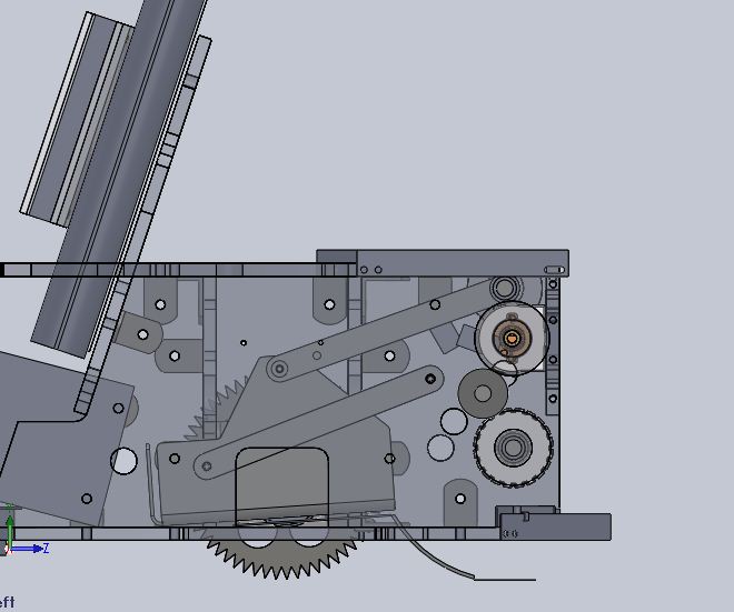
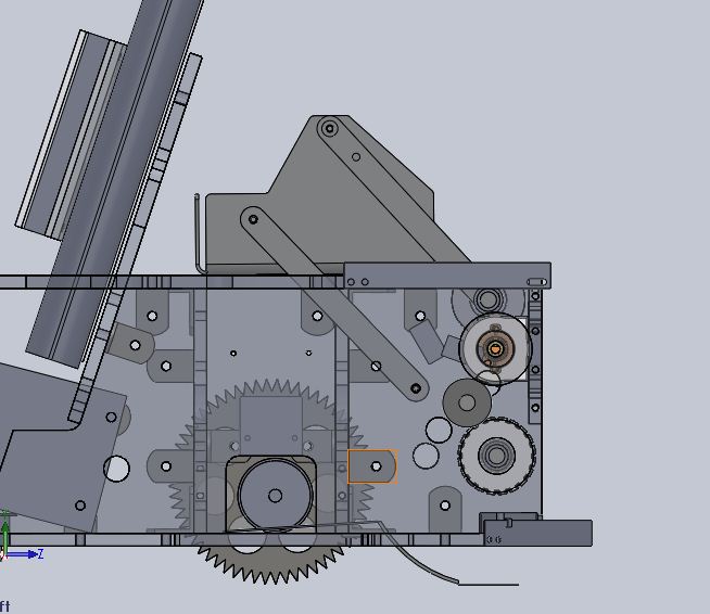
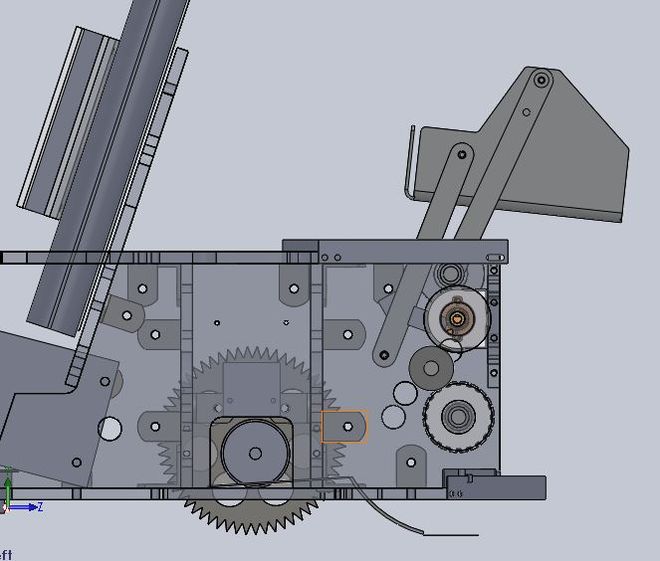
| - | + | The high level design of the robot's drive system consists of three structural boxes secured together in a line. The two outside boxes contain the drive motors, which are mounted to aluminum plates for strength. The central box forms the majority of the rest of the robot's structure and primarily contains the hopper. The three boxes are fastened together with steel brackets (to leverage the powers of the laser cutter and to avoid excessive tapping) and locknuts (to ensure the final assembly did not disassemble). | |
no slip wheels | no slip wheels | ||
Revision as of 02:28, 26 January 2011
Contents |
Team Members
- Leighton Barnes - Course 18, 2013 - Focused on sensor design and electrical work. Instrumental in debugging robot in all disciplines.
- Cathy Wu - Course 6, 2012 - Focused on major software components: vision, testing suite, multi-threading, ball collection and scoring behavior. Managed day-to-day activities and big-picture plans for the team.
- Stanislav Nikolov - Course 6, 2011 - Focused on major software components: overall architecture, wall following, stuck detection.
- Dan Fourie - Course 2, 2012 - Focused on mechanical design. Got things done extremely quickly.
Overview
Mechanical Design
Our robot was designed for robustness and reliability. Our robot serves as a reliable platform for the software vision and control systems. As such it should be sturdy, constructed quickly, have extremely low mechanical failure rates, be able to withstand hours of testing, and be robust to positioning errors. The robot's structural members will be built primarily from acrylic sheet. It will utilize a rubber band roller powered by a DC motor to collect balls and 4-bar linkage hopper actuated by a servo to get balls over the wall. DC geared motors will drive no-slip wheels.
Drive System
The high level design of the robot's drive system consists of three structural boxes secured together in a line. The two outside boxes contain the drive motors, which are mounted to aluminum plates for strength. The central box forms the majority of the rest of the robot's structure and primarily contains the hopper. The three boxes are fastened together with steel brackets (to leverage the powers of the laser cutter and to avoid excessive tapping) and locknuts (to ensure the final assembly did not disassemble).
no slip wheels
steel hubs
Electronics Mounting
Shock mounted laptop, monitor remove
ORC board plate
camera potting, adjustable
bump sensor suite
limit switches
battery slot
encoders
Scoring Mechanism
4 bar linkage
rubber band roller
Electrical Design and Sensors
Motor Controllers
Because our robot design required four motors (2 drive motors, 1 to pick up balls, and one to score them) and our Orc Board only features three H-bridges, we had to design an additional circuit to control the last motor. The motor that drives the roller in the front to pick up balls only had to go in one direction, so we chose that one as the one that would be driven by this addtional controller.
Our first attempt at this additional controller was just a 40N10 power FET whose gate was driven by the digital out of the Orc Board (with a protection diode accross the motor of course). As we learned with this first attempt, the digital out of the Orc Board is somewhere around 3.7V, instead of the nominal 5V, which could barely overcome the 2-4V gate threshold voltage of the FET (or any other power FET we had on hand). Instead of spending the time to build a gate driver to get around this problem we tried an L298 H-bridge package instead. This worked with the logic-level voltage provided by the Orc Board although we stuck to one directional capability in favor of using the standard four protection diodes instead of one.
Batteries
NiCd and Lithium options reasons we used lead-acid
Sensor Choice
bump sensors
break-beam
encoders
IR range-finders
gyro (or lack thereof)
Software Design
Architecture
cathy
vision driven
color calibration
state machine with bump detection and timeouts
sensor abstractions
Multi-threading
cathy issues?
States
cathy
what states
timeouts
Vision
cathy
color calibration
data structures
botclient
documentary mode
Wall following
stan
Stuck detection
stan
Testing
Testing suite
cathy
Mechanical Issues
ball jamming
eeepc access
battery placement
bump sensor coverage
pins falling out
motor failing
Failure modes and Countermeasures
Electric Issues
leighton
single-conductor wire and broken connections
uORC sample rate
power for fourth motor
Software Issues
cathy & stan
multi-threading
ball jamming
wall following
stuck detection
Performance
Suggestions
- Form a team early and commit to doing MASLAB for all of IAP. We formed our team before the start of the school year.
- Have a well balanced team. It's important to cover all grounds with software, mechanical, and electrical. Our 2 software + 1 mechanical + 1 electrical combination balanced us very well.
- Work really really hard and stay motivated. We pulled endless all-nighters and never gave up. We continued to pester the staff mailing list with questions and even took a day to set up some legit practice fields in 26-100 before the seeding tournament.
- Start before IAP and aim to have most of everything done in the first 2 weeks of IAP. Because we did most of the design before IAP, We managed to have a functional robot (not the pegbot) by the first mock competition, which helped us out greatly. We also were able to spend the last week and a half making fixes for various edge cases and had time to just polish up things.
- Test often and relentlessly. You'll find something wrong with your robot every time.


