Team Nine/Final Paper
Hanssusilo (Talk | contribs) |
Hanssusilo (Talk | contribs) |
||
| Line 56: | Line 56: | ||
== ''V. Conclusions/Suggestions for Future Teams'' == | == ''V. Conclusions/Suggestions for Future Teams'' == | ||
| + | |||
| + | |||
| + | [[File:funny1.jpg]][[File:funny2.jpg]][[File:funny3.jpg]] | ||
blahdiblahdiblah | blahdiblahdiblah | ||
Revision as of 03:47, 8 February 2012
Contents |
A MASLAB Tale or: the Souls of Three Engineers in Exchange for One Robot
TEAM 9: Officially “It’s Implied” (known in the streets as: “Blood Sweat n Tears”)
ROBOT: Officially “Rolo” (affectionately called “Hiccup”)
I. Overall Strategy
Of the four types of points that could be scored – short distance, long distance, green box, and possession – the type of goal we chose to work toward was the long distance shot. Our choice was not only due to the highest point-yield of long distance balls, but also because we believed that it would not require too much of a stretch in our mechanical design. Other important aspects of the physical robot we considered were speed and ball capacity.
As for the software design, we opted for a state machine approach and incorporated threads to coordinate the many tasks given to the robot. We took advantage of the python bindings available in OpenCV (Open Source Computer Vision) libraries for image processing functions.
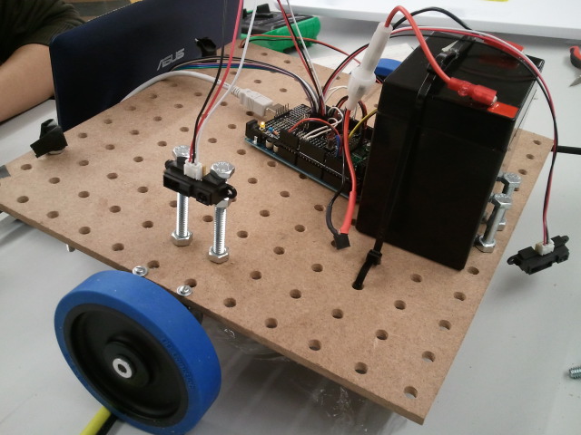
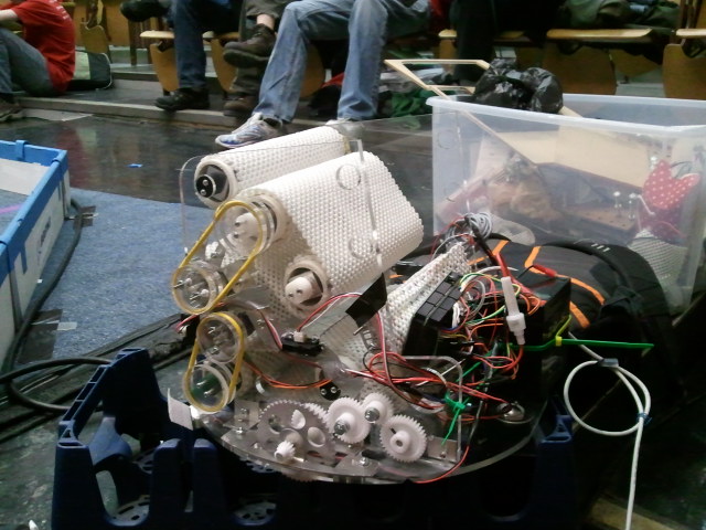
Pictured below: Pegbot!
II. Mechanical Design and Sensors
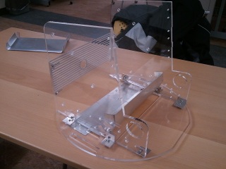
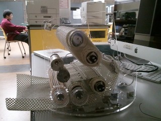
The main frame was cut from acrylic and the wheels custom-made with metal. Initially, we used thin sheets of metal to cut out the chutes responsible for guiding balls into and through the main frame. The middle chute persisted throughout the evolution of the mechanical design, but the bottom sheet was switched out for netting built of mattress gripper and accented with a slab of thin metal. When held taut by metal supports, the net’s flexibility provided an adjustable range of tension regardless of where in the chute the ball entered.
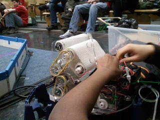
The key feature of Hiccup is the roller. Rollers are responsible for ball intake, digestion, and discharge; all other mechanical features, such as pulleys and metal slides, primarily serve to assist the rollers. We originally chose to use PVC pipes for the actual rollers and polyurethane cord as the frictional element which would be wrapped around either one or two pipes. Although we never ran into issues with the PVC, the wrapper went through several modifications as we attempted to counteract complications involving slippage and entanglement.
Not far into the building process, polyurethane cord was replaced by sheets of soft mattress gripping material, for increased friction over a larger surface area. From the start, the problem of having the wrapper stay in place as the two PVC pipes spun at high speeds for long periods of time was a major concern. Slippage was not seen to be an issue for single-pipe situations where one sheet of mattress gripper bound around one PVC pipe fared well over time. In an attempt to address this concern, our first design used strips of gripper material stretched across two pipes; these strips were separated by thinner rings of gripper material that were hot glued directly to the pipes. The thin rings were meant to confine the strips to smaller regions along the length of the pipe, lest they stray from their original positions via slippage over time. The rings were wrapped more thickly around the pipes than the strips, to make it more difficult for the potentially errant strips to escape. The strips, however, quickly twisted themselves into tight folds; indeed, the small width of the strips worked against our intended purpose and actually seemed to increase the troublesome mobility of the gripper material.
Observing the inefficacy of the hot-glued rings of gripper material, we abandoned the rings for whole-pipe covers, bound thickly around each individual PCV pipe. In addition to the individual pipe covers, each pair of pipes was wrapped by a single layer of gripper material. Using a single layer prevented the large wrapper from twisting within itself, and using one sheet as opposed to multiple strips tremendously simplified the construction process and reduced slippage. To alleviate the slippage, we planned to weave wire horizontally through the outer cover to decrease the flexibility of the gripper sheet in the horizontal axis.
With the webcam able to detect the robot’s environment at long distances, we decided to arm the front of the robot with four short-range IR sensors. Spaced our across the face of the robot, as on a spider perhaps, the short-range sensors enabled accurate wall-following. In addition to the IR sensors, our design incorporated two bump sensors, on the left and right sides of the robot’s face. Although the sensors themselves faced forward, the activating tabs were armed with wider shields, to increase the range of detection. Intended to park the robot against the yellow wall during the “find yellow wall” state, the left and right bump sensors were programmed to deactivate the left and right wheels, respectively, when contacted.
III. Software Design
Get on it Hans! a few CAD models would be lovely
IV. Overall Performance
'twas less than preferable
V. Conclusions/Suggestions for Future Teams
blahdiblahdiblah
