Team Nine/Final Paper
Contents |
A MASLAB Tale or: the Souls of Three Engineers in Exchange for One Robot
TEAM 9: Officially “It’s Implied” (known in the streets as: “Blood Sweat n Tears”)
ROBOT: Officially “Rolo” (affectionately called “Hiccup”)
I. Overall Strategy
Of the four types of points that could be scored – short distance, long distance, green box, and possession – the type of goal we chose to work toward was the long distance shot. Our choice was not only due to the highest point-yield of long distance balls, but also because we believed that it would not require too much of a stretch in our mechanical design. Other important aspects of the physical robot we considered were speed and ball capacity.
As for the software design, we opted for a state machine approach and incorporated threads to coordinate the many tasks given to the robot. We took advantage of the python bindings available in OpenCV (Open Source Computer Vision) libraries for image processing functions.
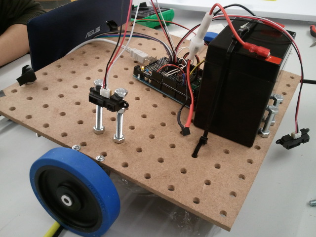
Pictured below: Pegbot!
II. Mechanical Design and Sensors
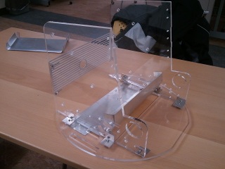
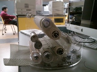
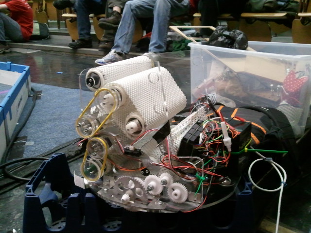
The main frame was cut from acrylic and the wheels custom-made with metal. Initially, we used thin sheets of metal to cut out the chutes responsible for guiding balls into and through the main frame. The middle chute persisted throughout the evolution of the mechanical design, but the bottom sheet was switched out for netting built of mattress gripper and accented with a slab of thin metal. When held taut by metal supports, the net’s flexibility provided an adjustable range of tension regardless of where in the chute the ball entered.
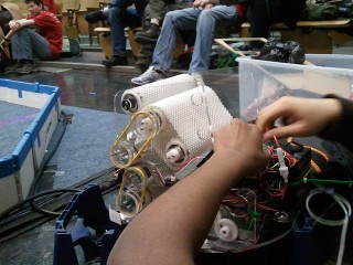
The key feature of Hiccup is the roller. Rollers are responsible for ball intake, digestion, and discharge; all other mechanical features, such as pulleys and metal slides, primarily serve to assist the rollers. We originally chose to use PVC pipes for the actual rollers and polyurethane cord as the frictional element which would be wrapped around either one or two pipes. Although we never ran into issues with the PVC, the wrapper went through several modifications as we attempted to counteract complications involving slippage and entanglement.
Not far into the building process, polyurethane cord was replaced by sheets of soft mattress gripping material, for increased friction over a larger surface area. From the start, the problem of having the wrapper stay in place as the two PVC pipes spun at high speeds for long periods of time was a major concern. Slippage was not seen to be an issue for single-pipe situations where one sheet of mattress gripper bound around one PVC pipe fared well over time. In an attempt to address this concern, our first design used strips of gripper material stretched across two pipes; these strips were separated by thinner rings of gripper material that were hot glued directly to the pipes. The thin rings were meant to confine the strips to smaller regions along the length of the pipe, lest they stray from their original positions via slippage over time. The rings were wrapped more thickly around the pipes than the strips, to make it more difficult for the potentially errant strips to escape. The strips, however, quickly twisted themselves into tight folds; indeed, the small width of the strips worked against our intended purpose and actually seemed to increase the troublesome mobility of the gripper material.
Observing the inefficacy of the hot-glued rings of gripper material, we abandoned the rings for whole-pipe covers, bound thickly around each individual PCV pipe. In addition to the individual pipe covers, each pair of pipes was wrapped by a single layer of gripper material. Using a single layer prevented the large wrapper from twisting within itself, and using one sheet as opposed to multiple strips tremendously simplified the construction process and reduced slippage. To alleviate the slippage, we planned to weave wire horizontally through the outer cover to decrease the flexibility of the gripper sheet in the horizontal axis.
With the webcam able to detect the robot’s environment at long distances, we decided to arm the front of the robot with four short-range IR sensors. Spaced our across the face of the robot, as on a spider perhaps, the short-range sensors enabled accurate wall-following. In addition to the IR sensors, our design incorporated two bump sensors, on the left and right sides of the robot’s face. Although the sensors themselves faced forward, the activating tabs were armed with wider shields, to increase the range of detection. Intended to park the robot against the yellow wall during the “find yellow wall” state, the left and right bump sensors were programmed to deactivate the left and right wheels, respectively, when contacted.
III. Software Design
Our state machine consisted of seven states: SCAN, WALLFOLLOW, CHASEBALL, CAPTUREBALL, DETECTWALL, ALIGNTOWALL, and LAUNCHBALL. In SCAN the robot would make rotate 360 degrees looking for any large enough blotch of red or yellow pixels. In CHASEBALL, it would approach a ball with proportional control. Once the red pixel size reaches a certain threshold (and presumably close enough), the robot charges forward at full speed to compensate for the ball positional error when it gets too close. The capture state called for code that would enable visual detection of red balls, and the shoot state required code that would allow identification of yellow walls. Although we chose to use the computer vision libraries of OpenCV in the search for optimized image processing functions, the python bindings were extraordinarily difficult to implement. Many simple and elegant methods for recognizing red balls and yellow walls simply had to be rejected after several attempts, either because of poor documentation, or because the functions did not behave in their expected manners.
After using an independent image editor to analyze the pixels of sample images taken by the webcam, we were able to determine the best HSV value ranges to detect red or yellow pixels. In our final code, red balls were detected by dividing the frame into several regions of interest, then searching each region separately for circles. The yellow wall was detected simply by searching for the average location of yellow pixels.
IV. Overall Performance
Due to the last-minute (quite literally) building of poor Hiccup, mechanical faults were the cause of Hiccup’s ultimate downfall in the final competition. In the first half of the round, downward facing screws on the ball transfer unit snagged against the carpet, restraining Hiccup’s attempts to charge a nearby ball. For the second half of the round, although we were able to patch up the misbehaving screws with tape, one of the gears connected to the left wheel came loose, and Hiccup came to a fatal standstill. Although we never did get to see the rollers in action at the same time as the wheels, the rollers were able to drive a ball successfully up and out during test runs pre-wheel-installation.
V. Conclusions/Suggestions for Future Teams
Isaac's Final Words of Wisdom:
"I was the mechanical builder,for the most part, for our team. I actually ran into a lot of problems throughout my building. First, sharp items are very sharp. I think I lost more blood during Maslab than anything else in my whole life! Sure, it gets your fingers thicker so it wont be easier to cut or poke next time, but my advice would be BE CAREFUL!!! If you work with knives, or even pliers, be wary of your fingers. The next thing would be about precision of holes and cuts. For our rollers, we used delrin and a U-bracket to keep the PVC pipe in place in between the two acrylic walls. However, when I was testing its spinning, the PVC pipe did not rotate in a proper circle. The reason for this is because when I drilled holes to attach the delrin to the U-bracket, the center of the delrin was not the center of the flat part of the U-bracket. So, when we put everything together,the rollers rotated awkwardly. If I were to do this again, I would not use U-brackets. Instead, I would make slits into either side of the PVC pipe, and slide a small, rectangular piece of aluminum into it, with holes already drilled to support the delrin, and bend the ends of the aluminum onto the PVC. This way, you can still adjust if you mess up drilling the holes into the delrin, and its easier to make it stay in place. This was actually the biggest mechanical issue I had, which took me a long time to fix. But, when I was making new U-bracket and drilling holes for the delrin, the instructor at the Edgerton Machine shop showed me techniques on finding exact measurements and centers. So, I was able to make much betters ones because of this technique. I don't really know how to describe it, but if you talk to Mark, or whoever is in charge at the Edgerton Machine shop, he/she can tell you many precision techniques. A minor addition since I am mentioning the Machine shop, try to have access to things like screwdrivers, hammers, power drills, ext. 24/7. I don't know how many times I couldn't build cause I didn't have a power drill. Luckily, my fraternity had one that they hid from me till the last 2 weeks of Maslab. If you cant do that, then try to suck up to the MITers people, and they might give you access to their machine shop (which actually is really good!) And knowing where all the machine shops are is a plus. (I know of the Edgerton machine shop on Vassar, Chemistry machine shop in the basement of building 4, the Central Machine shop in the basement of building 34, the Hobby shop, and MITers.) The last thing I would defiantly advise you to do is FINSH YOUR CAD MODEL EARLY SO YOU CAN START BUILDING EARLY!!! I feel if our CAD model would have been done earlier, we could have finished building the robot, and actually test it before the final competition! XD People may say that the program builds the robot, but if there is no physical robot, then your screwed!"
Staphany's Final Words of Wisdom:
"Ideas are dangerous. Why? They take time away from actually producing a functioning robot. Although my team was able to come up with some great ideas, we spent too much time trying to come up with the perfect plan. So our final product was not able to accurately display all the work we had put into it. Especially considering that I myself only learned how to program the previous semester and had never even thought about robotics before this IAP, I knew our team was not going to have the same level of experience as others. In addition, I think having one of our team mates drop out last minute did have a considerable impact on our ability to make progress when the going got tough. Considering how much we did accomplish with only three people, however, I am undoubtedly proud of us. So I suppose, to summarize, I want to advise teams to really consider their weaknesses before starting, and really be open to communication from fellow team mates. Keeping track of who is doing what, is not only important for organization and planning ahead, but also the key to maintaining a socially healthy team. And if a team mate is trying to follow the above advice, don’t resist. Your silence is worse than a rag of chloroform. And no, I’m not exactly sure where I was going with that analogy."
Hans's Final Words of Wisdom:
"Arduinos and Solidworks make me crazy. Take care of them before they eat you."
