Team Five/Journal
Jan 7--We went through the kit and started work on the Pegbot. Considered the thought of stacking the pegboards to create two levels, one for the laptop and the other for other components.
We also looked at the scoring boxes and updated our strategy after learning you can only score with your own balls and the only balls on your side to start are your own.
We saw that the boxes make it hard to "shoot" the balls to score. We got the Pegbot to move!
Jan 8--We attached an IR sensor to our arduino which allowed us to turn away from obstacles in the playing field.
We also decided to create a second level of pegboard to give us a place to mount our computer.
We spent some time cleaning up wiring from yesterday and figuring out the sizes of all the components so we can start planning where these would fit best on our final robot.
We set up GitHub and spent some time thinking about and implementing our existing software on our laptop.
We spent some time at the end of the day thinking about a reliable deployment scheme.
Jan 9--A slow day.
We spent time finishing dimensioning parts for our final CAD.
We also set up a firm schedule for the remainder of MASlab, agreed on our final design and decided upon a high-level software design.
We didn't change anything on our pegbot.
We spent time refining our vision software, which works on our personal computers, but not the lab computer yet.
We met with the staff and discussed our plans.
Lots of work in the coming days likely.
Now that we have it, here's our schedule:
| Date | Software | Hardware | Mechanical | Build | Checkpoint |
|---|---|---|---|---|---|
| 9 Jan | frame rate down | gyro/imu started camera ready for use | design outline | add gyro/imu and camera to peg bot | plan ready |
| 10 Jan | turn, drive toward ball, PID started | gyro/imu properly inputing and set | CAD robot parts figure out drivetrain etc. | evaluate what needs to be built and what can be bought scower the stock | turn, drive toward ball |
| 11 Jan | camera calibration, communicate between computer and arduino | design mounts | CAD robot and budget points/money reevaluate design | go through stock and establish modes of purchase add to budget | Be able to calibrate your camera quickly within 1 minute (ie for changing light conditions). Demonstrate your camera calibration by driving towards a green ball. |
| 12 Jan | Adapt software to new robot | reattach all to full bot | CAD robot | build period | |
| 13 Jan | finalize and apply design | ||||
| 14 Jan | MOCK 1 Start on button press, stop after 3 min | ||||
| 15 Jan | |||||
| 16 Jan | |||||
| 17 Jan | UPDATED PLAN | ||||
| 18 Jan | Mock Competition Day | NON pegbot robot built | MOCK 2 "Successfully calibrate within 1 minute, start on a button press, and stop after 3 minutes.
During the 3 minutes drive towards a red or green ball, then towards a yellow scoring wall. Optional: Pick up the ball. Optional: Score over the yellow wall with the ball." | ||
| 19 Jan | Slush Time: re-configure software, fix buggy mechanical parts, re-construction if necessary | ||||
| 20 Jan | |||||
| 21 Jan | |||||
| 22 Jan | |||||
| 23 Jan | Mock Competition Day | Deployment and storage built BUILD DONE | MOCK 3 | ||
| 24 Jan | Optimization Period Software optimization, mechanical design optimization, make small problems go away | ||||
| 25 Jan | |||||
| 26 Jan | |||||
| 27 Jan | |||||
| 28 Jan | |||||
| 29 Jan | IT'S THE FINAL COUNTDOWN | Seating | |||
| 30 Jan | |||||
| 31 Jan | IMPOUND | ||||
| 1 Feb | COMPETITION DAY | ||||
Jan 10-- Yesterday we decided upon a final mechanical design in principle.
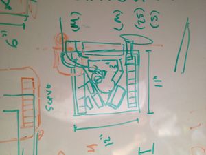
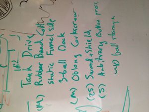
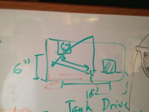
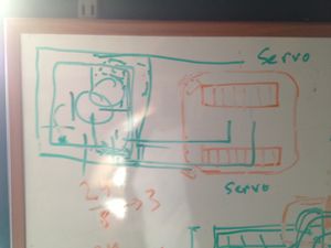
We uploaded diagrams of our design and started CADing smaller components so we can easily include them in our final CAD.
We researched our problem of not being able to communicate between the webcam, computer, and the arduino
Something funny happened, DanO plugged his computer into the arduino and it started moving. Hope that doesn't mess anything up.
Ariel's been working on optimizing the vision software so it will work reliably at any height without compromising speed.
Jan 11 -- Today we decided upon our Mock 1 strategy (super secret)
we successfully communicated between the camera, computer and arduino.
We're working on making sense of IMU input for positioning and accelerometer data.
We're getting the entire robot CADed so we can start construction this weekend.
We're also starting to think about things like optical encoders, drivetrain, and overall robot shape.
Our software is in good shape, so we're trying to work out issues with mechanical and electrical design.
We made a python-to-java socket which allows our java library to communicate with the arduino via PySerial
Got Checkoffs 3 and 4 Boom Got-em.
WEEKEND Jan 12 -- Today we started late, but we have made good progress so far.
We're making some decisions now regarding which programming language to use for our software.
Right now, we're seeing a tradeoff between latency and throughput with each language, but some give us better values for both.
Yesterday, we soldered the IMU together and are getting great, reliable data for the gyro and the accelerometer, although compass data hasn't been so great.
We're CADing our final design now which we agreed upon yesterday. Maybe these will come up here, maybe not.
We made a trip to the home depot for some materials which we can machine tomorrow. We're hoping to god that we can get everything we need for mock 1.
Jan 13 -- Lab Closed.
We worked from home on design problems, lots of cad. Anticipating mock 1 tomorrow
We went to Home depot and got necessary materials for the hull of our new robot.
Not much else today
Jan 14
MOCK 1
We spent this morning porting code so our vision would run faster.
We massively cleaned up wiring and moved the battery closer to the wheels which massively helped our motors.
We participated in Mock 1.
We want to have a complete physical robot very soon.
Jan 15 -- Today we stayed up late completing our full CAD of our robot.
We figured out a final deployment strategy
We visited a junkyard to try to find parts/inspiration to no avail.
We had a half-team meeting over Raising 'Canes across from Agannis Arena
We Tried to start building, but edgerton shop was closed.
Jan 16 -- Today we went into lab to figure out our strategy for Mock 2, specifically pertaining to mapping.
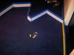
We built a mini playing field back at home base to do our own testing.
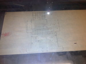
We FINALLY laser cut our base and mounts, so construction will begin later today!
We didn't get a chance to mill our wheel mounts today.
We brought all our materials home, and plan to work from there full-time.
Jan 17
We had to re-cut our base because some of the parts didn't fit well.
We spent today making our screw lift and mounting our electronics.
We made most of our mounts out of velcro. We're expecting to have use this as just a temporary fix.
We stayed up all night building our robot.
Jan 18
We woke up early to fix the caster wheels and fix our collection mechanism.
We participated in Mock II, however unsuccessfully. (Third Place)
We're planning on taking a break from the robot for a few days after this.
WEEKEND Jan 19-21
We spent the beginning of the weekend CADing a new design. The last one was a total failure.
We COMPLETELY altered our collection/lifting/storing mechanism
We changed where we're keeping our computer
We made our robot ever so slightly bigger. We'll have approx. 5 ball storage.
We re-cut the entire base and started building late Monday
Jan 22 -- Up early and building in the lab.
New wiring scheme, huge breadboard.
We spend time in the shop milling our last parts.
Huge construction push this morning so we can start prototyping.
We stayed up all night constructing and prototyping
Jan 23 MOCK 3
We got up and worked on software right up until the mock
Some of our components became broken so we had to make a temporary fix for the mock
we participated in mock 3
we went to the sponsor dinner and enjoyed foods
Tomorrow we will be re-building and re-imagining our deployment/storage/collection mechanism (all in one)
Jan 24
We re-made our lifting mechanism out of foam core to promote something temporarily more rigid
We re-evaluated our current design, we're gonna make our base stronger. Because we have a moving robot, we worked on PID stuff
Nothing else today
Jan 25
Bad Day. We had a team falling out after not being able to agree on specific mechanical components
We continued working on PID components and software throughout the day
Members of our tema stayed up all night CADing yet another design, this one stronger, swifter, and with more space for ball storage.
Jan 26
We finished our new design after much-needed sleep.
Jan 27
Laser cut the materials, and put all the acrylic parts together.
We have a robot that can move but can't pick anything up
Jan 28
Continued assembly
Tested Software
Built parts to lift balls
Ready to rock Seeding
FINAL PAPER:
Overall strategy
Team 5’s strategy originally was made under the assumption that both colored balls would be We decided that the blue bin had such a large reward that we should collect all of our color balls and score them in the top bin. We would also collect our opponents color balls and score them over the yellow wall at the end of the round to prevent our opponent from clearing the field. We would also release all balls possible from the button press. When we found out that, with high likelihood, the balls on our side of the field would, in fact, be of our color, we changed our strategy. We also made further changes when we discovered how difficult scoring balls in the top bin was. When our team realized that we didn’t need a storage mechanism that also sorted balls, our strategy and design greatly simplified. We decided that instead of trying to reach the top bin unreliably, we would try to clear the field and score over the yellow wall, which would allow our robot to be significantly smaller and shorter. We originally planned to have several button presses to try to get more balls onto both sides of the field and subsequently tried to score those balls. We felt that scoring balls over the wall, especially with the speed we were planning to have, would confuse the other robot. We also hoped that we could reliably clear the field and earn the 200 point bonus, while dumping all of our balls would likely not allow the other team to clear their field. As the competition progressed, we realized that our goals were more infeasible than we first planned. By the time the final competition rolled around, we adjusted our strategy to eliminate all button presses and just try to clear and score the 8 starting balls on our side. With up to 5 ball storage, we determined that we could outperform the majority of the field.
Mechanical design/sensor
The overall design of our robot evolved greatly throughout the competition. At first, our team wanted a 14”x14” square robot with top bin scoring and sorted storage capability. After we learned more about the competition semantics, we determined that such a large robot wasn’t necessary and that a smaller, swifter robot would have done just fine. We also made several discoveries while making our peg bot. For example, we determined that large robots can lead to unwanted results. We found that our peg bot couldn’t move if we placed our battery in some places. We found that if we constrained our robot to a smaller area, we eliminated the possibility of heavy elements in our robot having enough torque on our motors to cause our robot to become immobilized. We decided to have a 6”x7” design that stored only 2-3 balls and could move just fine on our stock motors. Our design eventually expanded to 10”x10” to allow for greater ball storage and to allow our electrical components to be more easily stored. We also discovered as the competition progressed that we could integrate several steps of our ball collection process. We found that building a rubber band roller was more difficult than originally determined. We also found that our vision code was reliable and accurate enough that we could drive within 1/2” of the ball on either side. We decided to integrate our collection and lifting mechanisms into one completely new design. We constructed a metal scoop for the balls that was connected to a high torque servo. This scoop lifted balls radially into our storage area, which was made out of aluminum ductwork. This ductwork snaked around the back of our robot to the opposite side, where a metal door connected to a servo kept our balls stored until we wanted to deploy them. Our drivetrain was very simple. We used our stock kit motors and geared them down just once to ensure we had enough torque to turn reliably. We also attached bearings to our main axle to ensure that it remained correctly aligned. Our sensor scheme was also incredibly simple. Our only sensors were the webcam, the gyro, and one IR sensor. We used the webcam for all vision and the gyro for all mapping/positioning. We also were able to make some determinations for planning and re-alignment from vision. We only used the IR sensor to ensure that we didn’t stay stuck against any walls. If our robot stayed up against a wall for more than 5 seconds, we determined that our camera was seeing over the wall and we would turn it around based on the IR reading.
Software The technology stack used for our code is as follows: Arduino (C) Python C++ The code is divided in to 3 segments: the sensory inputs + system actuation, the Python-Arduino interface, and the system control loop. The Arduino is responsible for all of the sensor data collection, motor controls, and servo controls. The majority of this code was given to us by the MASLAB firmware file initially provided. We did modify this file to read the gyro data to give 2-decimal accuracy. Furthermore, we added a small calibration phase to account for gyro drift. The only other small changes we made to the arduino firmware related to servo controls. While staying up late one night, we discovered a bug in the originally provided code that prevented servos from actuating along the desired ~180 degree span. It turns out that casting an 8-bit signed character to a 16 bit signed character is a bad idea! If an input signal greater than 127 was sent to the servo actuation function, the input would be interpreted as a negative number! We found this bug and mentioned it to one of the MASLAB staff. It was repaired shortly after. Our code actually just uses the fix as implemented by ourselves Our Python code is very minimal. Its primary purpose is to pull data from the Arduino interface (as provided by MASLABs starter code) and pipe it to C++ for advanced processing. We spent some time early on figuring out how to call C++ modules from Python. It turns out to be very easy and extraordinarily fast. Our python code is responsible for calling C++ image processing code, setting motor/servo values, and terminating operation at 3 minutes. Our main reason for using C++ is the great speed advantage. A quick benchmark showed that doing the processing in Python versus C++ was 300 times slower in Python while running identically optimized code. No processing was done in Python in our final implementation. The C++ code is our baby. It is beautiful. The C++ modules are split in to two portions: the Image Processing and the Behavior State Machine. The Image processing code takes the three stupidly simple steps of color classification, wall detection, and ball detection. Color classification simply requires pulling the image RGB values and classifying them independently of adjacent pixels. Each RGB value is classified in to a particular “color cone.” The color cones are simply vectors in the RGB space that span a volume of colors. If the RGB value falls within the appropriate color cone, then that pixel will be classified with that color. This code is fast! We’re talking 50 assembly instructions fast. So that’s plenty fast for our purposes. After color classification, we compute angles and distances to walls. Using the 3D rasterization rendering equations, we can convert differences in image y values to distances and image x values to relative angles. This basic conversion only works because we know about the heights of particular field elements and the field of view for the given camera. We successfully determined the distances to walls within 2 inches. Angles were determined to within 5% error which is plenty for our purposes. Finally, the ball detection code is also dirt simple. We run a simple blob detection algorithm to find massive blobs of green or red. If those blobs are big enough and satisfy basic criteria of ball classification, then we call them balls. This works exceptionally well since there are only red and green BALLS on the field and nothing else! The classification is rather loose and would not work for many other purposes. The ball classification criteria check for the ratio of width and height being near 1:1 and for the fraction of points within a square region being near pi/4. A perfect ball would have a width/height ratio of 1, and a perfect ball would occupy exactly pi*N/4 pixels from a sqrt(N) by sqrt(N) square. The final Image processing code required only 3 milliseconds of runtime. Our frame rate bottleneck was actually the camera capture time. Our camera would run at 30 FPS at most. Therefore, our final code only ran at 28 to 30 FPS. Finally, our code needs to use all of this wonderful image processing output to make decisions. We had a super simple state machine that contained only 4 states. The possible states were: Explore, Collect Ball, Deploy, and Reposition. The exploration state used data from the Image Processor to navigate the field based on immediate decisions. We had no aggregate map data, only immediate map data. If a ball was found, we would enter the ball collection state. If a goal was found and we had collected balls, we would enter the deploy state. The Ball Collection state focused on slowly approaching balls in a careful manner. Once our robot was close enough to a ball, we could easily charge towards it and collect it reliably. Some basic timeouts were set in this state to prevent us from ever getting stuck on unreachable balls. As another safeguard to getting stuck, we told our Image Processor to identify balls that were “unreachable” by our bot due to them being partially occluded or too close to walls. Upon collection, we return to the Exploration state. The Deploy state would focus on scoring. It would first check if there is a goal in its range of vision, and then prepare to score. We noticed that our scoring mechanism require precision, so we couldn’t simply score from any direction we wanted; we had to reorient our robot before scoring. Given our slick Image Processing data, we could actually detect the normal to walls and reorient ourselves accordingly. So, upon recognizing a scoring wall, we would reorient our robot 16 inches in front of the wall such that we were parallel to the normal of the wall. Afterwards, we would score by driving forward and opening the deployment hatch. The Reposition state focused on travelling in a certain direction for a set time, and the leaving the robot in a desired final orientation (or heading). When the reposition state terminates, it always returns the state machine to the previously inhabited state. For example, if we are repositioning our robot for scoring, we would return to the Deploy state upon completion of reorientation. Overall, our code was small, slick, optimized, and effective for the purposes of MASLAB. If this code were to be deployed on a larger scale system, it would have to be refactored heavily.
Overall Performance Our team feels that our robot massively underperformed at competition for a few reasons. Most importantly, We feel that our team wasn’t nearly as cohesive and prepared as we needed to be. Much of this had to do with our team composition and our team demands. We had only one mechanical engineer, and we couldn’t ever agree on a stable design. Our team built five separate robots in one month. Unfortunately, so many build periods in such a short amount of time gave our coders extraordinarily little time to code, which caused our robot to massively fall short of expectations. At the end of the competition, our robot could not move on the field because of a mechanical problem. On the left side of our robot, one of the bearings became loose, which caused our axle to become unstable. When our robot tried to turn, the gear system became disconnected because of the axle’s mobility. This caused one of our main wheels to be unable to be moved, which made our robot unmovable when it tried to turn in one direction, or made it turn around itself when it tried to drive straight. Other than our drivetrain, the mechanical aspects of our robot turned out fine. Our lifting scoop worked just as we needed it to. In fact, we found that at the length we built it, our servo could lift an entire textbook. Also, our storage and deployment mechanism was somewhat reliable. When adjusted correctly, the ductwork acted like a continuous ramp, and the deployment door worked properly. The only issue with the ductwork was that it was flexible, and its position was not definite. This caused it to sometimes become turned out of position, which let balls become stuck when waiting for deployment. Code-wise, our robot performed flawlessly. Our vision code not only distinguished game elements, and created localized mapping, but did so at 30ms/frame. Our state machine had flawless transitions and our robot was able to re-align against the scoring wall perfectly.
Suggestions For next year there are a few things specific to team five that we would like to see. Firstly, we’d like to see the opportunity for great strategy to trump a “lucky” design. This has more to do with the in-game choices. For example, when our team believed we would regularly be handling our opponent’s balls, our strategy and design was far more complicated and complex. While we know that such a suggestion may seem crazy, moving away from a simpler game, but we feel that when students are prompted with difficult design choices, their final products are more interesting. The only other suggestion is that we’d like to see the staff keep teams from making bad decisions and forming bad habits early in the competition. The staff has spent more time around the competition and can understand when the students are making a mistake by a particular re-design or code tweak. These changes might be crucial to a teams at the end of the competition, but we feel that at the beginning of the competition, it is essential to make a design and stick with it, leaving a lot of time to make minor changes down the road if need be. Overall, Team 5 greatly enjoyed MASLab and some members of our team will likely participate again.

