Team Four/Journal
| Line 39: | Line 39: | ||
We planned on having some actual pictures to upload to the journal showcasing our beautifully complete base, but we'll just upload some screenshots of the solidworks design instead. | We planned on having some actual pictures to upload to the journal showcasing our beautifully complete base, but we'll just upload some screenshots of the solidworks design instead. | ||
| − | [[File:Completebase.png|300px|thumb| | + | [[File:Completebase.png|300px|thumb|center|Complete base design.]] |
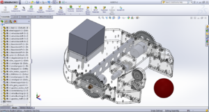
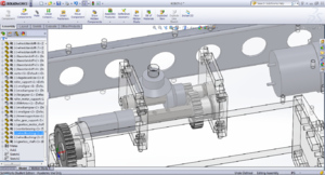
This is our base assembly, made using a combination of t-bolted acrylic plates and standoffs. The goal with this design was to keep as many of the heavy parts as low in the frame as possible. This should help keep the center of mass of our [very] tall robot low. As such, every motor is mounted below the top of the base, and a central gearbox is used to transfer the motion through a right angle to power the hopper. We spec'ed out a motor to use in this gearbox that had double the power required (determined with some conservative calculations), but we don't know exactly the final speed (and therefore the gear ratio) we'd need for the central brush. To that end, this gear box was designed to have multiple configurations; we can assemble it to produce either a 1:1, 1:2, or 2:1 ratio between motor and end shaft. | This is our base assembly, made using a combination of t-bolted acrylic plates and standoffs. The goal with this design was to keep as many of the heavy parts as low in the frame as possible. This should help keep the center of mass of our [very] tall robot low. As such, every motor is mounted below the top of the base, and a central gearbox is used to transfer the motion through a right angle to power the hopper. We spec'ed out a motor to use in this gearbox that had double the power required (determined with some conservative calculations), but we don't know exactly the final speed (and therefore the gear ratio) we'd need for the central brush. To that end, this gear box was designed to have multiple configurations; we can assemble it to produce either a 1:1, 1:2, or 2:1 ratio between motor and end shaft. | ||
| − | [[File:CentralGearbox.png|300px|thumb| | + | [[File:CentralGearbox.png|300px|thumb|center|Adjustable gear ratio right angle gearbox.]] |
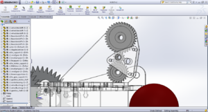
A similar design strategy was used for the gearing on the front roller. There are holes in the roller mounting plates that can accommodate gears in either a 3:1 or a 3:2 gear ratio, without changing the motor, roller, or plate position. This should allow us to play with different roller speeds without much hassle. | A similar design strategy was used for the gearing on the front roller. There are holes in the roller mounting plates that can accommodate gears in either a 3:1 or a 3:2 gear ratio, without changing the motor, roller, or plate position. This should allow us to play with different roller speeds without much hassle. | ||
| − | [[File:RollerGearbox.png|300px|thumb| | + | [[File:RollerGearbox.png|300px|thumb|center|Adjustable gearing for the front roller.]] |
Revision as of 16:58, 14 January 2013
Day One
Today is one of those days where everything that can go wrong, will go wrong. In lab we promptly shorted out our battery (luckily we had properly hooked up the fuse) and right before finishing code for checkpoint two we accidentally plugged something somewhere it wasn't supposed to go and released the magic blue smoke from our motor controller. ヽ(`Д´)ノ ┻━┻
The end of the day is starting to look up though. We have most of the critical modules of our robot SoldidWorksed, as of right now we're in the process of adding in the specifics such motor mounts and standoffs. Hopefully by the end of tomorrow we will have everything finalized so we can cut out the relevant parts out of acrylic in Edgerton. We found these amazing motors that fulfill all of the requirements for operating our hopper and ball collection system, and put in an order for it. It should arrive sometime between Friday and Wednesday.
Tomorrow aside from lecture we plan on replacing our motor control and getting checkpoint two to work before leaving. I am also going to Edgerton to get training so I can use their laser cutter.
Day Two
Today was much better than the day before. We got our power cable re-soldered to the switches make sense, making it impossible to short out our board like we did the day before. Lesson learned. Q(^_^Q ) After a little fiddling with our code we finally got our checkpoint two to work. It turned out our bump sensor needed a pull down resistor, because otherwise it was acting as an antenna and every time one of us got close to the robot it activated the switch, which gave the appearance that the code wasn't working. Just goes to show you all the small things you don't really consider while soldering up electronics that can really mess you up. We'll be twice as vigilant in the future.
At our meeting tonight we got our strategy and mechanical design mostly flushed out. Our cad model is coming along, and if we get our t-bolting to work the first time we can have a completed robot base within the next two days! ;) We also got a jump start on playing with vision code, however no significant progress has been made so far.
Day Three
Today was a rather successful day. We have a moderately complete Finite State Machine laid out, and we have planned much of our software architecture. We were able to complete the day's checkpoint without much hassle and are working to implement some of the suggestions offered by the staff regarding both the software and mechanical aspects of our design.
In addition, we have made some good progress in our vision code. By the end of the night we were able to identify red blotches in static images, and have almost finished implementing some basic edge detection with a Hough transform. Early tomorrow we should be able to identify red balls in images and determine their location relative to the front of the robot. We expect to apply this code to the video stream from our webcam at some point tomorrow as well, allowing us to implement a basic PID aiming function and align the front of the robot with the balls on the field.
In addition to this software progress, the mechanical design has made a lot of headway as well. We've decided to use a total of 4 motors and 2 servos to control our mechanisms. This number has been changing a lot over the last few days, but we believe that we have settled on a design that is both robust and mechanically simple(r). We've replaced the small, shady kit motors with more powerful Trossen motors from the stock bin for use in our drive train, and relegated one of the kit motors to the front roller. We designed a right angle gearbox for the motor we ordered yesterday, allowing us to power the hopper from the base. There will also be room in the base to mount the Arduino and the Dagu controller. This will keep our power and mechanical elements more consolidated and our total center of mass much lower. In addition, the basic design of the hopper is complete, and over the next few days all of the acrylic plates can be cut out and we can start assembly. Hopefully we will have a drivable base with a working roller on the front by Friday!
Day Four
We made a lot of progress today, both mechanically and with software. We were one of only three teams to successfully complete the 4th checkpoint, and our robot (still unnamed) could chase red balls around the practice field by means of vision control. We had code running that would analyze a video frame, find a red ball, determine a relative angle between our heading and the ball, then adjust motor speeds to aim at that ball. This was only a basic algorithm, however, and would simply stop moving when it couldn't see any balls. We used some simple proportional control to adjust motor speeds and hope to update this to some smoother PID code tomorrow. Our code was processing the full HD resolution from the webcam during our tests today, so the program was only getting about 10 cycles per second. We are going to downsize this resolution a bunch to try and improve this speed.
On the mechanical side of things the base is completely modeled. The two drive motor assemblies, front collection roller, central gear box, and battery housing are ready to be cut out at Edgerton tomorrow morning. We will also be stopping by the Hobby Shop to cut out our wheels and some sheet metal parts, as well as to manufacture some hubs and shaft sleeves. We hope to have the base assembled by the end of the day tomorrow!
Day Five
It's the weekend, so today was inherently pretty slow. While we planned on getting most of our things cut today, many small problems, such as where to place mounting holes for our hopped and designing our hopper supports, that we didn't notice until today kept cropping up. This prevented us from moving forward on construction. However, the good news is that by Monday all of these kinks should be ironed out and if we wake up early enough we can have our actual robot base done and use it for mock competition 1, which will be a huge advantage.
Another good note is that because our robot worked so well today we have a rather large head start on working on our vision code. We cleared the checkpoint of following green balls with ease, and got our frame-rate up. At this pace I am very hopeful for our performance during mock 2.
Day Six
We were lied to. As it turns out, Edgerton does not have a laser cutter, and we were not able to cut out our plate parts for the base. We are lucky enough to have a friend working in a lab with a laser cutter who is willing to help us out, but we have been delayed significantly. We have to wait until Monday or Tuesday to have the parts finished. So instead of having a functional base in time for Mock 1, we are now planning on having a completed base by Mock 2 on Friday. Hopefully this base will also include a front ramp, roller, and funnel, so that incorporating the hopper will be easier later on.
We planned on having some actual pictures to upload to the journal showcasing our beautifully complete base, but we'll just upload some screenshots of the solidworks design instead.
This is our base assembly, made using a combination of t-bolted acrylic plates and standoffs. The goal with this design was to keep as many of the heavy parts as low in the frame as possible. This should help keep the center of mass of our [very] tall robot low. As such, every motor is mounted below the top of the base, and a central gearbox is used to transfer the motion through a right angle to power the hopper. We spec'ed out a motor to use in this gearbox that had double the power required (determined with some conservative calculations), but we don't know exactly the final speed (and therefore the gear ratio) we'd need for the central brush. To that end, this gear box was designed to have multiple configurations; we can assemble it to produce either a 1:1, 1:2, or 2:1 ratio between motor and end shaft.
A similar design strategy was used for the gearing on the front roller. There are holes in the roller mounting plates that can accommodate gears in either a 3:1 or a 3:2 gear ratio, without changing the motor, roller, or plate position. This should allow us to play with different roller speeds without much hassle.


